Functionality of a Circuit Board
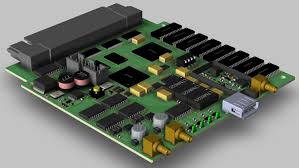
A circuit board is a crucial piece of equipment that provides power and energy to different parts in an electrical device. It is composed of various components such as resistors, capacitors and transistors that ensure the functionality of the board. The components are essential to a PCB’s performance, but sometimes they can malfunction and cause problems with the entire device. Here are some tips on how to test the functionality of a circuit board and locate any issues that may be occurring.
The first step in testing a circuit board is to conduct continuity tests. This involves using a multimeter to measure resistance or voltage drop across an electrical connection. This will help identify any open or short circuits that could prevent the circuit board from working properly. This is also a good time to check for any other issues that could potentially be affecting the board’s performance such as corrosion or loose connections.
If you are having difficulty locating the short circuit on your electric circuit board, you can try a visual inspection by looking for any hot spots that may be present. Be sure to wear rubber gloves when handling components as they may still contain electric charges. Also, make sure you disconnect the power supply before conducting a visual inspection.
How to Test the Functionality of a Circuit Board
You can also test the circuit board for any faulty resistors by using your multimeter’s diode mode. This will allow you to determine the forward voltage drop on the cathode and anode pins of the component. This is important as it helps you determine whether the resistors are good or bad by comparing the reading to a graph that is available on the component’s datasheet.
A capacitor is a vital part of any electronic system, as it stores and releases electric charges to control current flow. If the capacitor is faulty, it will not be able to release these electric charges and can affect the overall functioning of the circuit board. A faulty capacitor can also cause noise and harmonic frequencies to interfere with the signal being transmitted over the circuit board. This can be a big problem if the faulty capacitor is located near a IC or other sensitive component that can be affected by noise and harmonics.
Another method to test a circuit board is to use an ICT (integrated circuit testing) machine. This is a machine that simulates the circuitry of a printed circuit board by sending data to its CAD software. This allows the CAD software to display the logical representation of the circuitry as well as provide simulation models and footprints for the PCB layout. This can save you a lot of time when you are trying to troubleshoot a complex circuit board. However, it is not a substitute for a thorough test of the component itself or the connections between components.