
PCB Stiffener Can Improve SMT Process Stability
When designers first developed printed circuit boards, they based them on rigid substrates that were unbendable. As the industry grew and evolved, manufacturers began to make flexible PCBs by adding traces sunk into flexible strips. These new boards could flex in multiple directions and connect with rigid ones to form a complete board assembly. A key component to enabling these flex-to-rigid transitions is a PCB stiffener. But how do these stiffeners work, and what design considerations should a designer take into account?
Stiffeners are usually fabricated from FR4 glass epoxy, polyimide (PI), or aluminum. The choice of material is based on the stiffness and weight requirements. FR4 is typically used for flex-to-rigid transitions because it provides a high level of rigidity while maintaining flexibility. It also has good electrical insulation properties and resistance to heat, chemicals, radiation, and other harsh environments. PI and aluminum, on the other hand, offer superior mechanical strength and are great for use in areas that require high levels of durability and resistance to corrosion.
During the fabrication process, the thickness of a stiffener can be altered to meet the exact specifications of the flex-to-rigid transition zone. This can be achieved by varying the number of layers in the stiffener or using different materials for each layer. Stiffeners can also be laser cut to accommodate mounting features like openings, perforations, and connections points for component attachment, hardware placement, and linking with the rigid PCB.
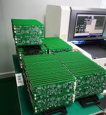
How a PCB Stiffener Can Improve SMT Process Stability
A flex-to-rigid PCB must have stiffeners to ensure the integrity of the board, especially during the manufacturing and inspection processes. One of the most common reliability problems that can occur is broken copper traces during bending, which may result in circuit failure. This can be avoided by routing flex traces perpendicular to the bend line and by ensuring that all arcs have tapered transitions. Additionally, the CAD tools should be able to support group routing functions that can carry buses across the flex zone.
Another important factor in preventing the breakage of flex circuits is the presence of strain reliefs on a pcb stiffener. These should overlap the bared coverlay by a minimum of 0.030″ to relieve stress on the copper. Additionally, the stiffener should be thick enough to resist abrasion and stress from the assembly and reflow processes.
It is crucial that designers communicate these specifications to their fabricators so that they can provide the correct flex-to-rigid stiffener for a successful production. Rush PCB offers intelligent manufacturing data formats that help communicate these specifics to the fabrication house for a seamless product. This allows the fabricator to avoid unforeseen manufacturing issues that can delay or even compromise the end-product. For more information, see our blog on How to Ensure a Smooth Rigid-Flex Stackup.