
Design a Flex Circuit
A flex circuit is a flexible printed circuit board that can be bent or curved, usually to fit into a smaller space. They can be made from rigid or flexible materials, and are often used in mobile phones, laptops, digital cameras, and other consumer electronics. They are also frequently used in aerospace and military applications, as they can withstand a wide range of environmental conditions. However, there are a few things to keep in mind before using a flex circuit.
First, you will want to consider your design and the requirements for the project. In general, a flex circuit must be able to withstand bending and twisting, and it should also be able to meet the performance requirements of your device. To ensure that your flex circuit meets these requirements, it’s important to choose a material that is both flexible and durable. This means that you should look for a copper film that has been rolled and annealed, as this will be more flexible than an electro-deposited layer.
Another important consideration is the thickness of your flex circuit. While there are many options available, you’ll want to pick a thickness that will work well for your application. Typically, thinner traces will be more flexible, while thicker traces will have greater durability. Finally, you’ll need to decide whether or not you want a stiffener on your flex circuit. A stiffener will help to strengthen the flex circuit and protect it from damage during manufacturing.
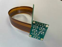
How to Design a Flex Circuit
The next step is to select the base and copper foils for your flex circuit. You’ll want to choose a base material that is both flexible and durable, such as polyimide or liquid photoimageable. The copper foils will be placed on top of the base material, and then a coverlay is applied to the front and back of the flex circuit. This covers the signal and power planes, and it also protects the traces from damage during manufacturing. The coverlay can be either a silkscreen or a solder mask, and it can be colored with different colors to match the component color.
To improve the flexibility of a flex circuit, it’s a good idea to use wider copper traces. This will allow the flex circuit to bend without damaging the traces. You should also make sure to avoid placing critical components or features directly in the flex ribbon bend areas. It’s also a good idea to separate analog and digital signals onto different layers, and to use cross-hatched copper patterns for ground planes in both the flex and rigid sections of the circuit.
Rigid-flex circuits are hybrids that combine the benefits of rigid and flex PCBs. They consist of a network of rigid PCBs that house components, and flex circuits that connect them. They are commonly found in commercial and military electronic devices, and they can withstand a wide range of temperature, humidity, and vibration. In addition, they are lightweight and offer more streamlined circuitry than traditional rigid-flex boards.